Generator Help Needed

I'd forgotten that you have an odd end plate. Notice that the adjustable brush is close to the GROUND brush in the first picture you post a link to in #17. As you move the adjustable brush AWAY from the ground brush the output should increase.

So, looking at the generator from the front (pulley end) you will have to rotate the adjustable brush counter clockwise to increase the output. This is opposite the direction you move the standard Model A generator adjustable brush to increase the output.

Is the armature VERY near to the field poles? It's very important that there is very little air space between them. If someone turned the armature to get rid of rust then they have ruined that part. How did you install the poles and get them REAL TIGHT?
 
Tom,

everything that you mention has been done, and as I said, all elements have been measured for continuity and isolation after mounting. the only thing that might be is that I could have reversed the polarity of the fields, as i did not specificly mark each end of the fields while disassembling. anyway, I have connected the assembly according to the diagram shown earlier in the thread. In any case, I will check that. Please do not forget that the thing is outputting a 13-14V open circuit when the fields are supplied externally, but nothing when they are connected to the third brush.

How many volts are you putting to the field windings when you do it externally? Also, when you do it externally is the field wire still attached to the adjustable brush, and the adjustable brush still rubbing on the commutator?

Is the case and field windings identical to the normal Model A case and field windings? Do you have a picture of the case and field windings?
 
Tom

Supplying the fields separately, I disconnected it from the third brush.
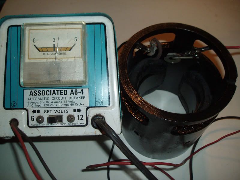
Used a 6V battery charger ( pos gnd) Fields drew between 3 & 4 amps


As far as I can see everything on the genator except the inside of the end plate is standard. the armature does not appear to have been been turned down.
Could perhaps do better at tightening the fields. Will try.

Am not with the generator just now. Will inspect the armature- field gap when I get back.
 
Did this generator ever work while you owned it? It's always good to know what was done since it last worked. Did you see my new posting about using a growler? Does that help you any?

The low voltage at the adjustable brush is of little concern right now because the adjustable brush picks up only a percentage of the output, depending on how far the brush is moved away from the ground brush. Lets call the ground brush ZERO potential and the ouput brush X volts. The generator field has a residual magnetism that will give the generator an output of about 1/2 volt, so now the X volts at the output brush equals 1/2 volt. If the adjustble brush is close to the ground brush then it may only be picking up 10% of the output, or .05 volts. But even this small voltage is fed right back to the field windings to increase the magnetic field, which then increases the output, which then increases the field strength even more, etc, etc. Now you can see why in an unregulated charging circuit, if you didn't have the battery to control the voltage, it can reach high volts and burn out bulbs, etc.

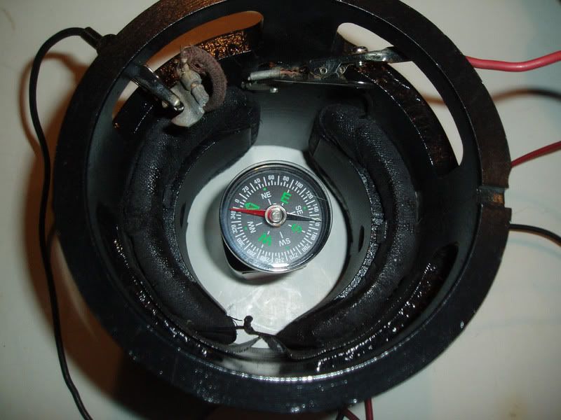
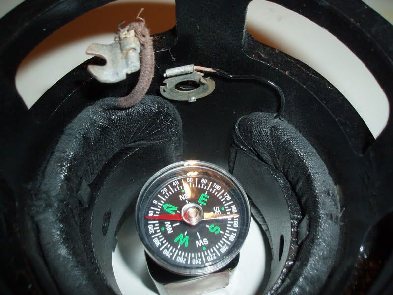
So far your field windings sound good with a 3 to 4 amp draw at 6 volts. I'm wondering if the end plate might have the brushes located in the wrong position to pick up the voltage from the commutator segments. If this generator used to work with this end plate, then I'm wondering if the field windings are in the wrong location or wound in the wrong direction. I have done some checks using a compass to show how one field is NORTH and the other field is SOUTH. I'll see if I can find the pictures.
 
Last edited:
Field1.jpg


Field2.jpg


Field3.jpg


Here's 3 pictures showing how I check the field windings for current draw and also showing the residual magnetism. If I lift the compass out of the center and place it along the left side or right side the needle would still be pointing the same as shown. Remeber, the outside will be the other polarity, but the needle will also have the other end next to the metal.

If you have one field coil wound in the wrong dirrection then you could have the same polarity on both inside poles, yet draw the correct amps when checking with the battey charger.

Notice that this is the later style (after Feb 1930) and has the output terminal at the rear and the field ground terminal is under the insulating washer for the output stud.
 
Tom,

My field windings look exactly the same as the ones in your picture.

The wires go on and off the coils in the same direction as on yours. I inspected this, and by the right hand rule I saw that the fields of the two coils are definately aiding not opposing each other.

The diffrence I see is that the grounded and live ends of the fields are reversed with respect to your photo. However this should fit with the end plate where the live and grounded main brush positions also are swapped.

I guess one thing that I do not undstand, is how the third brush manages to make a closed circuit. Where does the current flowing through this brush come from, as there is no brush at the immediate opposite side of the armature.

When the third brush at a certain instant is connected to a specific armature winding, there is no connection to a brush at the other end of that winding, how is the other end of the winding getting to the grounded main brush to make a closed circuit. Are all the windings on the armature somehow connected ? If so, how ?
 
"When the third brush at a certain instant is connected to a specific armature winding, there is no connection to a brush at the other end of that winding, how is the other end of the winding getting to the grounded main brush to make a closed circuit. Are all the windings on the armature somehow connected ? If so, how ? "

The armature windings are connected in a series of coils, as you will see two wires soldered at each commutator segment. So the other end of the variable brush circuit is the GROUND brush, and the movable brush picks up more voltage as it's moved away from the ground brush.
 
Generator Still Not Working

Took all windings to a knowledgeable restorer, who have previously been doing auto electrical systems for a living. He confirmed yet another time that both armature and fields were sound.

However, when I put it together-it still doesn't work. Here's the situation again :

- Generator motors the correct normal rotation direction.
- When field coils are disconnected and supplied by a separate 6V Supply it works perfectly, charging about 10 Amps.
-However, with the field coil back on the third brush the generator will not get past 0.4V output.
-Have also tried to supply the fields directly from the main brushes - still nothing more

It seems that the thing just will not work itself upwards when its on its own. Polarization ? That should have been taken care of both when motoring and when I supplied the fields from a separate supply. Agree ?
 
Here is a idea, send the generator to Tom, That is if Tom will take it. Im going to try and sweet talk him to work on mine:)
 
If I lived closer to Tom, sure that was what I would have done !

Anyway, seems that I have got it working now !!

Problem was due to my generator having an unusual set of brush holders. -See my other post
http://www.fordbarn.com/forum/showthread.php?t=56208.

Still, I had the internals of the generator connected according to the Normal type of brush holders. With the normal brush holders, the third brush can be set close to the output brush. However with my brush holders the third brush will not get close to the output brush, so the feed voltage to the fields will never get very high. On the other hand my third brush holder will get very close to the ground brush, so with this setup one needs to connect the fields between the generator output and the third brush, not between the third brush and ground as normally is the case.

Inspection of the picture below will explain.

Wired the fields as explained above, and Generator now outputs in excess of 10 V, depending on which speed I run it at. Have not yet tried hooking it up to the battery to measure the charge, but I think that the problem is nailed now.

Anyway thanks a lot to Tom for all his explanations, they have really stimulated my thinking, and feel I have learned and realised a lot about generators and their service in the process . Thanks !
 

Attachments

  • bilde1.jpg
    bilde1.jpg
    70 KB · Views: 41
I see a lot of paint. Try scraping the paint around the field wire / ground wire that goes to the case. Some times we don't see the little things.


p
 
On starters & gens always sand the mounting flanges & housing ends as the grd circuit is as important as the hot side.
 
Back
Top