Worn Distributor rotor

Byron Warwick

Senior Member
Yesterday on an extensive road trip I experienced intermittent engine miss fire. On opening the distributor I found that the metal contact strip to the coil, that is on the rotor was worn back about 5/16 to 3/8". Enough that there was very little metal left to make contact. I did clean it up and made it home, but had to go as low as 30mph to keep it running. I had not experienced that before. Does anyone have an explanation. What do you think Bubba?
Thanks Barners, Byron W.
 
No really sure which engine you have but looking at you avatar it is a helmet distributor.
If so here are the two styles of rotor with the larger ring being the earlier one. The carbon button on the coil rides on this brass ring and needs some care from time to time etc. If the button was rough, or loose and arcing the damage would happen at this ring........
Wear would allow the button to fit the ring with light contact and arc burning as it was driven.......:eek:
 

Attachments

  • IMG_0793.JPG
    IMG_0793.JPG
    91 KB · Views: 91
Sorry Bubba I didn't say that it is a 1954 Canadian Mercury engine with the distributor on top. Look forward to your advise. Byron.
 
A little different discussion using the more conventional ignition loadamatic disributor...
All wear is caused by heat and arcing in these units. In a perfect world voltages are kept below 8000 volts and secondary air gaps are under control. Plugs are set at .025 ( flathead standard) and rotor air gap is at a minimum .010 or so. Rotor gap can never exceed plug gap... All wires ( coil wire etc) is tight and in good condition as loose fitting or burnt ends make voltages go upward ( could be 20,000-30,000 volts !!!) Carbon button in cap needs to be in good shape as well.
Any resistive change in the secondary ignition causes higher than normal voltages , higher voltages makes part become burnt and defective.
You need to check all the above .
I just looked at a friends flathead here in the parking lot and the coil wire was burnt back approx 1 inch from the inside the coil!!!!
Let us know what ya find....
 

Attachments

  • IMG_0794.JPG
    IMG_0794.JPG
    96.7 KB · Views: 115
Bubba:
The first thing I found on the first stop, was both the A and B post wires were not tight. So maybe that could allow the higher voltage and it arced the end off the rotor's coil contact. Later, on a second roadside look, when I removed the dizzy cap, I found a lot of carbon and a build-up of Metal? flakes and carbon around the coil post inside the cap. After I cleaned these things up, and found I had no spare rotor I buttoned it back up. I was pleasantly surprised that it restarted and so I proceeded to continue back home, about 50 miles. i have new parts on order from my local Car Quest and will get them on Thursday. Should I remove the whole dizzy and clean out any more carbon that may have settled to the bottom?
I'll look at all the parts as I remove them. I hope it doesn't happen again, but I'll monitor it more closely, in the future. Thanks, and cheers, Byron.
 
Well, here is the rotor with the contact plate worn down. the one on the right is an old one with the contact metal the correct length. Any explanation for the cause for future reference?
Cheers, Byron.
 

Attachments

  • Rotors.jpg
    Rotors.jpg
    39.5 KB · Views: 154
Well, here is the rotor with the contact plate worn down. the one on the right is an old one with the contact metal the correct length. Any explanation for the cause for future reference?
Cheers, Byron.


Yep the high voltage is at the center carbon button on the rotor thats why its black...
could be defective carbon contact or someone may have got the cap and rotor misalighed when installing the cap....
In any case replace both with a napa heavy duty cap and rotor and you should be fine . Also make sure all wire connections to cap are all the way in and tight.......
 
I'd like to find a way to check the clearance between rotor and the terminals in the cap. It's hard to see through those black caps. I've bought new caps and rotors and install them with dist on bench, rotate the dist by hand and hear the rotor hitting the terminals, so grind a little off rotor, BUT I'm still guessing the clearance. There has got to be a to check them. Walt
 
Thanks for the input Bubba.
I am wondering if the distributor shaft is worn. I'll keep an eye on it, to see if there is any more wear.
Cheers, Byron.
 
I'd like to find a way to check the clearance between rotor and the terminals in the cap. It's hard to see through those black caps. I've bought new caps and rotors and install them with dist on bench, rotate the dist by hand and hear the rotor hitting the terminals, so grind a little off rotor, BUT I'm still guessing the clearance. There has got to be a to check them. Walt

Since you have the distributor out, what if you used clay or play-doh inside the cap? Might take a couple tries to get it not to peel off when the rotor swipes past but I think a large thin layer over the inside of the cap at each post might work. I was searching threads for plug wire when I saw your query.
 
Thanks for the input Bubba.
I am wondering if the distributor shaft is worn. I'll keep an eye on it, to see if there is any more wear.
Cheers, Byron.

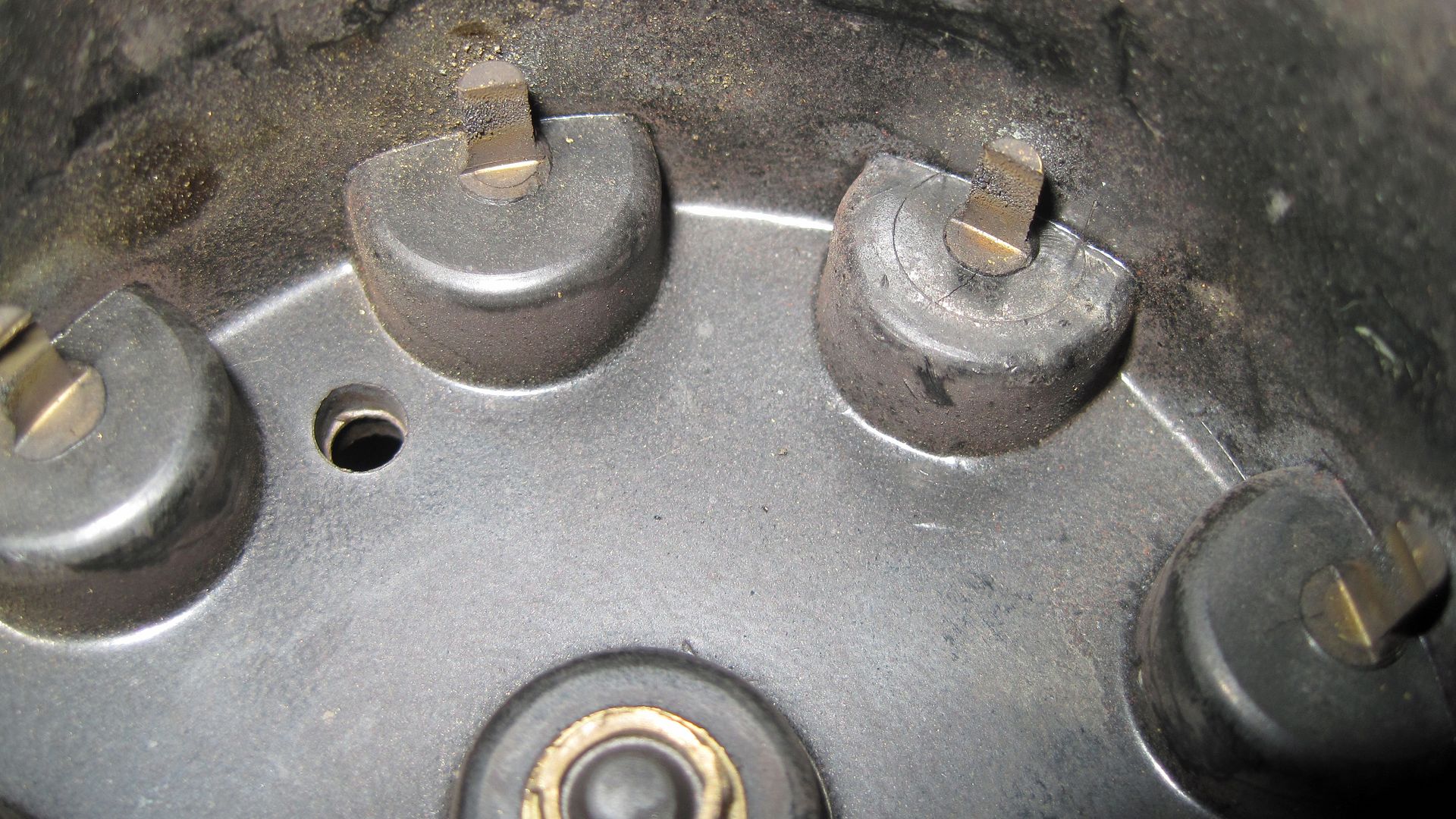
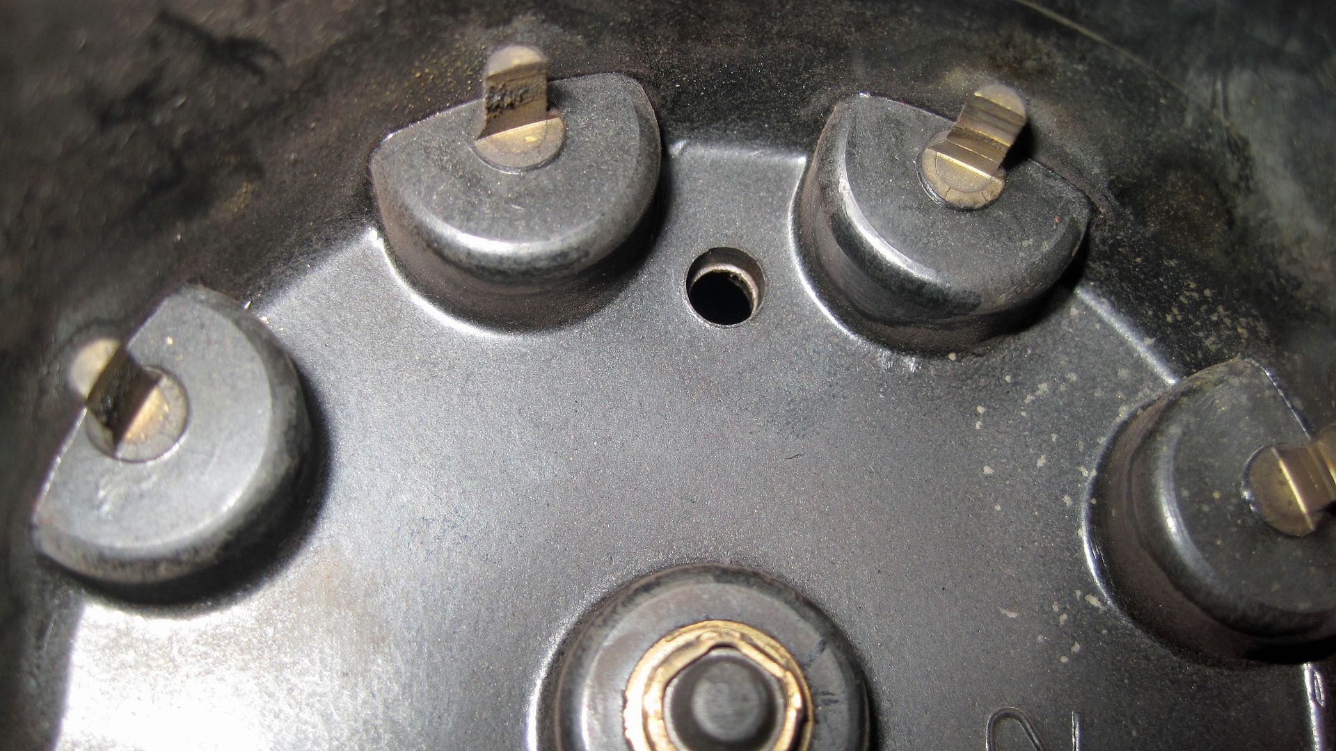
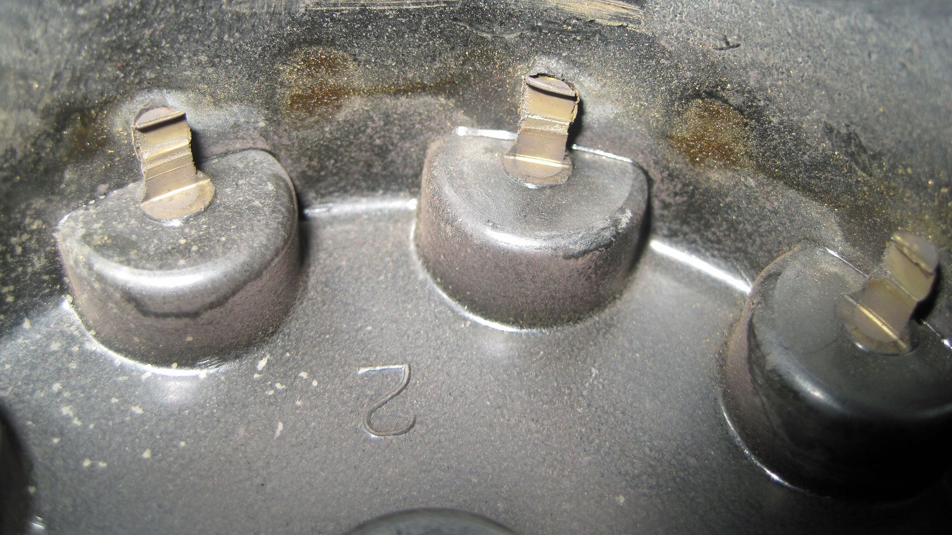
Here's what happens when the distributor shaft wears. The rotor starts hitting the contacts in the cap. New cap doesn't help. Gotta replace or rebuild distributor. Bubba did mine. Has worked great since.

IMG_3733_zpsd6bc2e7a.jpg


IMG_3734_zpsdc3d4974.jpg


IMG_3732_zps71faf91b.jpg
 
Last edited:
To calculate the clearance between the end of the rotor and the contact inside the distributor cap is quite straightforward.

Get the dimension between two OPPOSITE contacts inside the distributor cap and divide this by TWO....this is the radius.

Carefully measure from the centre of the rotor to the tip. Subtract the two and the result is the gap.

In order to determine the working radius of the rotor, make up a spigot to fit inside the rotor with a projection of say 0.050" and remember to subtract 0.025"

Got it ?
 
To calculate the clearance between the end of the rotor and the contact inside the distributor cap is quite straightforward.

Get the dimension between two OPPOSITE contacts inside the distributor cap and divide this by TWO....this is the radius.

Carefully measure from the centre of the rotor to the tip. Subtract the two and the result is the gap.

In order to determine the working radius of the rotor, make up a spigot to fit inside the rotor with a projection of say 0.050" and remember to subtract 0.025"

Got it ?

Got it? (no) not the last line about the spigot. Walt
 
1. a small peg or plug for stopping the vent of a cask.
2. a peg or plug for stopping the passage of liquid in a faucet or ****.
3. a faucet or **** for controlling the flow of liquid from a pipe or the like.
4. the end of a pipe that enters the enlarged end of another pipe to form a joint.

England must use a different definition!
 
Like Walt, I'd like to know how to reasonably check the clearance between rotor tip and cap on a 1941 type distributor. I just put them together and they work, but I've never known what the "Standard" should be.
Thanks Bubba for posting that the gap should be less than the plugs.
Good to know
Jim
 
Walt....here's a UK spigot . Spin one up on your lathe; or your neighbour's.

The large diameter slides in to the rotor.....measure from the small end.

Got it ?
 

Attachments

  • rotor.jpg
    rotor.jpg
    123.5 KB · Views: 22
  • spigot 001.JPG
    spigot 001.JPG
    68.5 KB · Views: 21
What about the caps that are off center? These turn up fairly often.
Yes you can measure the radius and rotor, this will give you a clearance measurement if the cap sits where it's ment too. But often times the cap or the cap contacts don't sit where there ment too. When bad, you'll feel the rotor hit the contacts on one side. Normal course of action is to file the rotor end to clear, and fit the parts. How do we know the rotor gap on the side that didn't hit? I'm gonna guess this gap is often too big, and made bigger by the filing done to clear the hitting side of the cap.
In this scenario, if we measured the rotor and the cap contact radius, the resulting measurement would have given us a clearance, the actual parts would hit.
Then there are the caps that we fit, test it don't hit, and run um. Still could be real tight one side and loose on the other. Here we fitted a "good" cap and are happy. Have we? Or have we just fitted a part that is gonna shorten the life of the other parts in the ignition system?
The day's of opening a good manufacturer parts and them being what they are ment to be vanished a while ago. And with it went a good chunk of reliability.
Kinda like the idea of a ring of something soft that can be put in the cap, cap fitted to distributor wit rotor, turn the drive, pull cap and measure. This is obviously easier on some ignitions than others, and the soft stuff easy to clean out and soft enough to not hurt stuff but stiff enough to keep its form.
Martin.

 
How about this possibly stupid idea. Take a thin strip of scotch tape and stick it to the rotor. Reassemble and turn it by hand...if it doesn't hit, add another strip until it does hit. Measure the stack of tape.
 
Back
Top