Valve springs

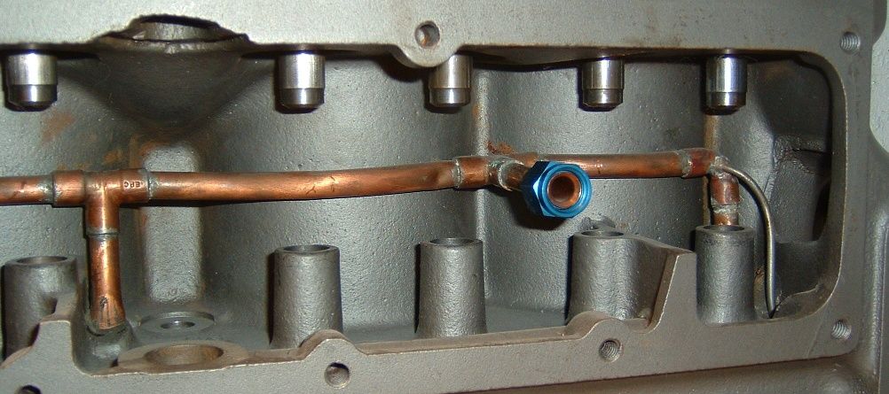
The main difference in mine is the tubes run on the opposite side of the valves or just behind the valve cover. I don't see any way to drill spray holes in the tube to spray the valves. I will try to get some pics tomorrow. The cam bearings don't have any external way to oil. I don't see any way for them to oil. Many things about this engine baffle me.
 

I don't quite understand the 'dump excess' part- it would overflow the dam as normal.

James, Do you have a picture of the epoxied-in-place pressure plumbing? I see no reason why you can't add a tiny hole or bleed line to just flood the chamber. Are the end bearings of the cam also pressure fed? A 3/32 hole would provide quite a chamber flood even at idle, without excessively dropping the running pressure. Especially with that big pump.

Here is a picture of a pressure A block now on my bench, also with epoxied feeds. The main line, which follows the cylinders behind the valves, was epoxied in first. Then small tubes were fitted into the elbows at the ends to feed the cam bearings.

Just because your tubing is epoxied in place shouldn't stop you from adding a tiny bleed line or hole to flood the chamber. I was thinking about drilling the valve chamber floor of this block for drainage and adding nozzles to squirt the exhaust valves from the rear. I really want to get rid of the flooded chamber! I'll add another 1/8" tube with a swaged 0.020 hole to squirt the cam gear. Please excuse the spots of flash rust. It's been sitting two months, I haven't been feeling well.

PressureOilManifold.jpg
This motor uses a sealed valve cover without the return tube like a B engine. The only way the oil can get out of the chamber is over the front dam and Ford found in the early days, that won't work well. That is why the T and the B both have holes in the floor of the chamber along with the mist helps to lube the valves. In the T, the valves are lubed by this hole expressly since it has no pump or dippers originally.
 
James, in the pressurized engine I built 2 years ago with a crossed drilled crankshaft I did three things in/near the valve chamber to try and ensure that the valves and cam bearings where well oiled. First I drilled a .055" bleed hole in the front of the valve chamber oil line directed at the back of the cam drive gear. This should produce extreme amounts of oil mist just in front of the valve chamber. Secondly I drilled another .055" bleed hole in the base of the oil pressure relief valve below the valve seat and directed to the back of the valve chamber. And thirdly, the oil pressure relief valve should also create oil mist when it opens at slightly above idle RPM's. I'm running the Bill Stipe oil pump and my hot engine idle oil pressure is #22. At 1000 RPM's I'm at max oil pressure of #35 so the pressure relief valve is open above 1000 RPM's. In the early stages of my engine build, when I was trying to determine the proper size of the bleed holes I was using a drilled dipper tray. I saw some slight cylinder scoring that may have been from the lack of oil mist reaching the cylinder walls, so I decided to replace the drilled dipper tray with the original non-drilled tray. Haven't seen any scoring since then.
 

Attachments

  • DSC03179small.jpg
    DSC03179small.jpg
    69.7 KB · Views: 100
Last edited:
Hey Al,
So you are saying that... you still have the rod cap dippers ...in pressured oil engine? Usually, in pressured oil engines, the dipper is eliminated and the dipper rod cap hole (bottom) is filled to keep pressure in/directed as needed i.e.- in rods/mains?
 
About 25 years ago,I converted an A to pressure oiling,but it is so much easier to convert the B to full pressure.
 
James, sounds like that motor is a hot mess :eek:

Pete
Confusing, but I will work it out. I put the empty block on the mill table and found the block deck to be good. About .003 difference from the front to the rear and less across. It does have a little dish in the middle at the distributor hole. Everything is coming together and as soon as I figure out this oil problem, I am putting it back together. The run in stand is going to be the best test, easier than putting it in and out of the car.:rolleyes:
 
I am confident that you will get it all dialed in James. I take it we are going to keep the Winfield head on it ?

Pete
 
hardtimes, I'm using Rich Falluca's inserted rods which have dippers. They are closed off when using insert bearings but will still splash lots of oil around the crankcase from the dipper tray. There is no oil delivery to the wrist pins and I didn't feel that enough oil was being thrown from the pressurized rod journals to oil the cylinders walls, that is why I decided to replace the drilled dipper tray with an original undrilled one. And besides, I didn't design my oil system with racing in mind.
 
I put the empty block on the mill yesterday and found the block measures 11.489 on one end and 11.491 on the other. There is +.004 difference from the front to the rear on one side and -.003 on the other side. The 11.491 end is flat but there is .0035 dish at the distributor hole. I will deck the block and cut the piston tops about .025, no more. The holes are square with the deck.

James,
You taking compression out of the engine?
Did you CC the engine?

You could run an additional(1/4") line in the chamber, as a "spray bar",
too all the springs/guides, with a hole in the floor for a drain in the back.

Also, you could drill a small hole(about 1/8") in each lifter boss, for
additional oil and control.
Dudley
 
hardtimes, I'm using Rich Falluca's inserted rods which have dippers. They are closed off when using insert bearings but will still splash lots of oil around the crankcase from the dipper tray. There is no oil delivery to the wrist pins and I didn't feel that enough oil was being thrown from the pressurized rod journals to oil the cylinders walls, that is why I decided to replace the drilled dipper tray with an original undrilled one. And besides, I didn't design my oil system with racing in mind.

I noticed some scuffing on my pistons and did the same thing you did, I put a undrilled dipper tray in for the same reason. At this time I'm using the same connecting rods as you.
 
OK, here is where I am at with this engine. The valve chamber has been without oil for the life of this conversion. When they drilled the dipper tray the mist the builder expected disappeared. The oil is plumbed to the bearings and has left the valves without oil to the point the guides are worn out. #3 exhaust was worn from .343 to .383. That's .040 oversize. The rear seal was a mess and the thrust bearings were junk. I have thus far replaced the MG midget rod bearings they used for the mains with a set of AER bearings which the original builder claimed were "junk"?. I also removed the front thrust which was 2 piece steel and brass, screwed to the cap with nothing on the top in the block and the brass thrust seal krap that is sold by the dealers and less than marginal in this engine. I replaced these with a full circle floating rear thrust and a front half thrust which are all cut into the block and non rotational. I used an original steel seal in the block and have sealed it for oil control. I drilled 2 holes in the tubing running through the valve chamber which are directed at the #2 and #3 valve springs for lubrication and filling the chamber so the cam can get some oil and the gears are lubricated. The worst thing that I may have to change would be to put the original valve cover and return tube back on instead of the custom aluminum cover which has no return and the hole in the block is blocked off.

Looks like I am closing in on fixing most of the problems. I don't know how this builder can stay in business doing work like this and charging such prices. I'll try to post some pics tomorrow.
 
Back
Top