
V8 Camshaft Bolt Pattern

It is a Pilot engine but that makes no difference really.
In order to preserve material around the lower stud holes each cylinder centreline has been moved 1/8" inward and bored out to 3.1/2", breaking into the water jacket. Liners have been pressed in and laser welded in place, top and bottom, to restore block rigidity. The finish bore will be 3.3/8" with a 4" crank.

But we were talking about camshafts.
A cast of the timing gear teeth was made in polyurethane which sets hard and is dimensionally stable. That is used as the key for the jig for drilling extra holes in the gear to allow cam timing to be advanced or retarded by anything up to 5 degrees (camshaft degrees).
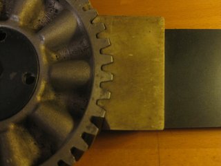
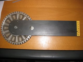
IMG-3631.jpg


IMG-3636.jpg
 
Very interesting. When you say move the bores “inward” 1/8”, do you mean inward along block length or inward of the “V”? Questioning because inward to the V will change pistonTDC to cam timing slightly, also change left and right banks differently. Would have to lay this out in CAD to really see what it does. Is this also reason for adjustment of cam timing?
 
The cylinder offset is inward toward the centre of the V, so, as you say, TDC in the right bank (looking forward) will be "late" while that in the left bank will be "early".
My initial concern derived from the simplistic thought that the ratio of cylinder offset to crankshaft throw circumference would need to be translated to valve and ignition timing, ie. 3.6 degrees early and late, so a strange new camshaft would be required and two distributors, one for each bank.
However, some fairly simple algebra and trigonometry convinced me that the effect was negligible and could be ignored, the new TDCs being only about one degree each side of standard: half a degree at the camshaft and distributor.
 
Last edited:
It is a Pilot engine but that makes no difference really.
In order to preserve material around the lower stud holes each cylinder centreline has been moved 1/8" inward and bored out to 3.1/2", breaking into the water jacket. Liners have been pressed in and laser welded in place, top and bottom, to restore block rigidity. The finish bore will be 3.3/8" with a 4" crank.

But we were talking about camshafts.
A cast of the timing gear teeth was made in polyurethane which sets hard and is dimensionally stable. That is used as the key for the jig for drilling extra holes in the gear to allow cam timing to be advanced or retarded by anything up to 5 degrees (camshaft degrees).

IMG-3631.jpg


IMG-3636.jpg

That is kind of a neat setup - "One Jig Rules Them All" LOL
 
Nice work, Neil. That laser welding sounds high tech. Will you be sharing any of the big inch 21stud build?

Mart.
 
I'm assuming your engine is for the Batten Special?

Will the restoration to the earlier configuration, include going back to the '35 type grill shell?
 
Yes, Frank, for the Batten.
I've always believed that the present radiator shell was a 1932 design, truncated. What have I missed?

Today:
Radiator-shell.jpg


1938:
Boz-at-Donington-crop-2.jpg
 
Last edited:
Back
Top