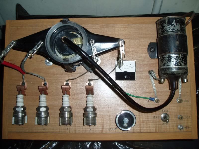
I've had some requests for more pictures, so I've decided to post 6 more pictures here. Notice the wires to the coil primary terminals cross each other. That's because I first built this machine using a coil with the negative post on the other side. Since my cabinet was marked already I had to cross the wires to keep all the markings correct when I used my slant pole coil. The red plastic sleeve on #1 is needed when I connect the inductive pickup on my scope.
I made the cabinet out of some old sheving I pulled out of someone's trash can. I was riding my bike when I spotted some nice looking boards and figured even though the shelf unit was broken, the shelves would be good for something.
Here you can see I use a clothespin with a screw to create a 1/2" spark, and hold the pencil lead in the spark path to demonstrate coil polarity.
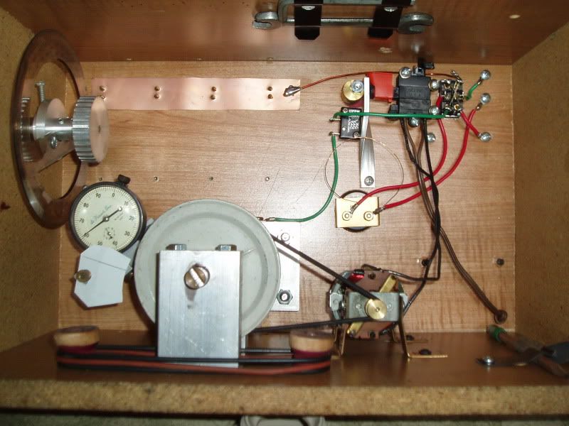
Here you can see how the dial indicator and degree wheel are safely stored away when not in use. I cut a wood spool in half and use it to store spare drive belts (long O rings). This way if the drive belt breaks, I can just slip on a new one with no down time.
This is an overall view of the bottom showing the clips to hold an Allen wrench, used to tighten the distributor set screw, and a 1/2" open end wrench, used to mount the dial indicator. I also have the pencil clipped in place.
Here you can see the cam I made to operate the lever which turns on the microswitch first to feed power to the coil, then turns on the variable speed switch to power the motor. The thin copper wire is a shunt I had to make for the 5 amp guage, which is used to check the coil draw.
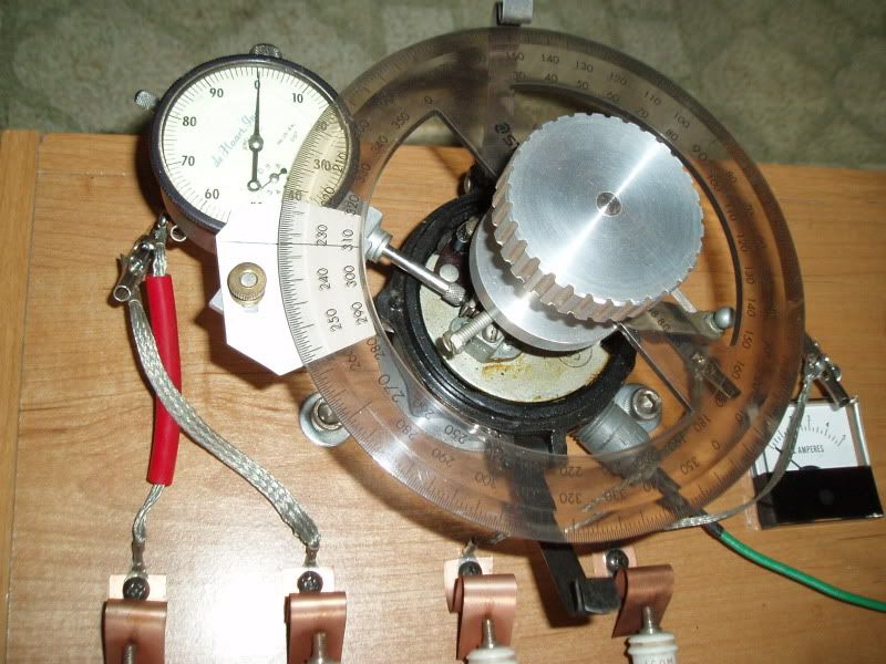
Here you can see the dial indicator mounted as well as the degree wheel, which I use to check the accuracy of cams. The most important cam check for an even firing engine is that each lobe opens the points exactly 90* apart. For the degree wheel to measure accurately I had to make sure it was exactly centered on the aluminum mount I made for it. By turning on the power to the coil I can read the 4 amps it draws, then as soon as the meter goes to zero I read the degree wheel and go to the next lobe and read when the meter goes to zero again. Hopefully it will be exactly 90* from the previous lobe.
By reading when the points close, a 4 amp reading, and when the points open, a 0 reading, I can figure the dwell, which is the time in degrees that the points are closed.