Lubricate Powerhouse

mmindling

Senior Member
Hi, this is Martin in Ohio.

My question is regarding the simplest way to lubricate a Powerhouse generator?

My Powerhouse is an early version with a side mounted cutout, five brushes, early pulley and cad plated end cap.

It's off the car right now and on my bench. Have not attempted to remove the pulley but can see a serrated cap underneath the pulley.

What's involved in removing the pulley? Does the cap cover the front bearing? How to lube the front and back bearings?

Really don't want to disassemble the unit completely, if possible. My latest efforts at tinkeritis have ended badly.

As always, appreciate the advice.

Martin, in beautiful Watertown, Ohio, on the fringe of Appalachia.
 

Attachments

  • Model A Engine Close Up LS.jpg
    Model A Engine Close Up LS.jpg
    72.3 KB · Views: 115
Martin,
I did tinkeritis when I lifted the top of my mother in law's oooooold toaster to put a new cord on it. 38 individual guard wires fell on the bench!!! Guess who bought her a new toaster~~~~~~~~~~~~~~~~~~~~Bill W.
 
The powerhouse has two bearings. You can get to the larger front one by unscrewing the serrated cap behind the pulley. Be careful as it is pretty soft and you can chew it up easially. I recommend that you dissemble the unit and replace the bearings with sealed bearings. The small bearing is the same as the pilot shaft bearing in the fly wheel. Here are part numbers of bearings. They are easy to find and you will never have to lube them.
Small: 6203.2RSR.C3 (*** Bearing)
Large: 6204.2RSR.C3 (*** Bearing)
 
PH1.jpg


There is no shortcut, but the job is easy. Remove the rear cover, then remove the 2 screws on the output wire strap (buss bar). Remove the screw for the field wire, then remove the 3 screws holding the brush holder assembly to the body. Be sure to use a good screwdriver that correctly fits the screws, so you don't have to push into the screws to remove them. The bakelite is very fragile and often cracked or broken. JB Weld can be used to repair broken pieces of bakelite. Set the brush holder in a safe place. Unscrew the bolt holding the armature in place. Then install a 1/4 - 28 bolt about 2" long. Hold the armature over your lap by grabbing around the commutator. Tap on the bolt and the armature should come loose. Remove the bolt and armature.

Don't let someone turn the commutator. They almost never need to be turned, but may need to be undercut by hand and polished on the lathe with crocus cloth.

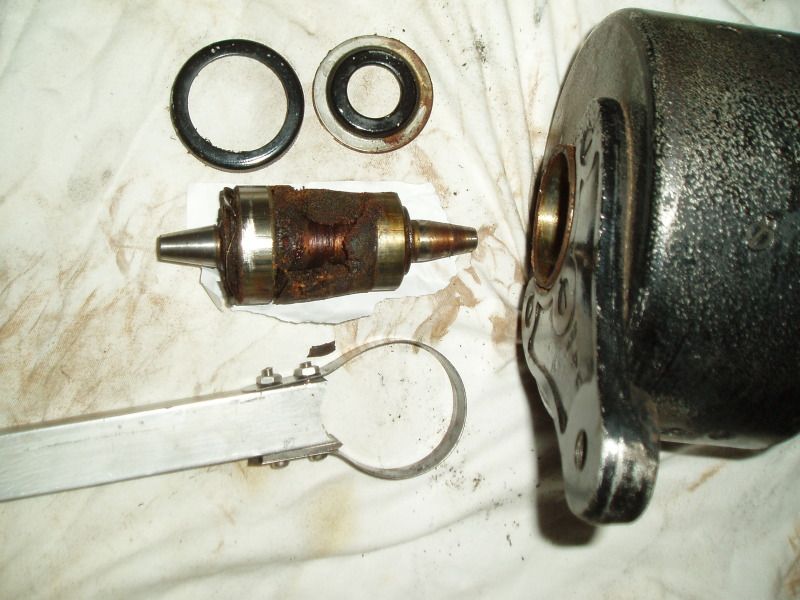
Remove the pulley bolt and install the 2" bolt, which was used on the rear. Tap it with a hammer and the pulley should come loose. Set the bolt and pulley aside. I made a special wrench to remove the serrated ring which holds the bearing/shaft assembly in place. A piece of thin steel banding strap pinched tight with a vice grip should work for you. If you don't have banding strap then a large channel lock plier might work for you. Don't use a hammer and chisel like so many have in the past.

Once the ring is off then the bearing assembly can be pushed out the front. No need to remove the steel slingers and bearings, if the bearings feel good. Clean the old grease off with gas and compressed air, and blow dry. I repack the bearings with Mystik JT-6 High Temp grease. I hand pack the bearings the same way I do front wheel bearings. I also put some grease in the space between the bearings, then reassemble. Note that the rear bolt is longer than the pulley bolt.

PowerhouseGrease1_zpsd9fa1d4d.jpg


Here's the tool I made to remove the front nut. I did a repack on this generator a couple weeks ago. The bearings felt good and still had the original grease, but it was getting thick and dry. With the new grease it shouldn't need any further attention in my lifetime.

Your engine compartment looks nice.:) Your fan belt looks like it's tighter than it needs to be.:confused:
 
Last edited:
I have rebuilt quite a few 3 and 5 brush generators; like Gary, I replace the open bearings with sealed bearings. I also clean and reinsulate the field coils and armature using Red Insulating Epoxy as some of the old insultion has dried out and flaked off leaving some of the wiring exposed ; just trying to avoid any shorts or open circuits. Check the twists between the field coils as have found a few loose.

Good luck,

Ron
 
That appears to be a very thick shim behind the starter, which flywheel and starter drive combination are you using?

That got my attention also. I think it looks like the rear half of the flange was masked off and not painted. I always paint the complete flange. The 3 lock washers easily cut through any paint and carry good starter current.
 
Rich in Tucson, Tom,

The flywheel starter combination is a multi-disc flywheel plus an early Abell starter with the original drive and gear set.

My understanding, and I could be misinformed, is that the Abell starters were fitted to the flywheel housing with a thick steel shim.

Please advise if this is incorrect?

As to painting the shim, also would like to know if it should be painted or what is the appropriate finish?

As to the Powerhouse lubrication, thanks for all the advice.

Regards,

Martin mmindling@aol.com
 

Attachments

  • Model A Engine Close Up LS.jpg
    Model A Engine Close Up LS.jpg
    72.3 KB · Views: 23
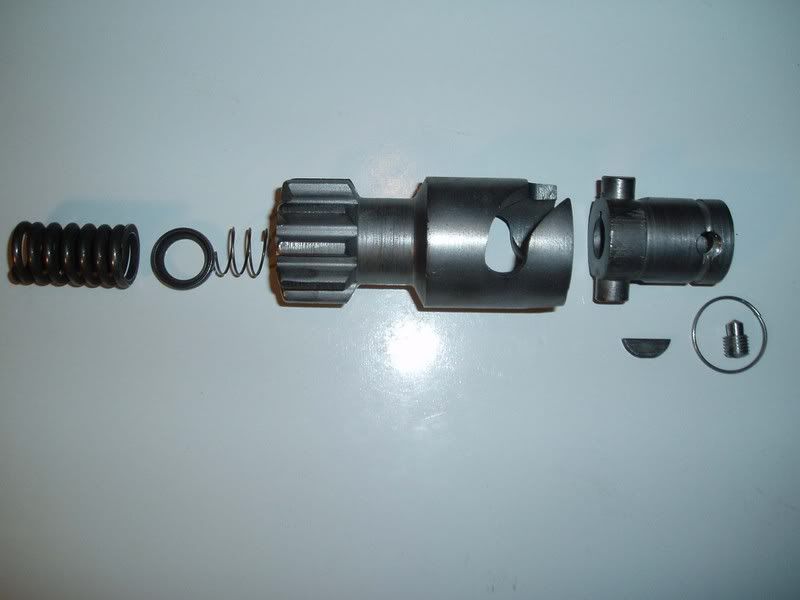
I don't have the information at hand on the shim and pinion to flywheel ring gear clearance. I think original metal shims were about .006" or .010" thickness, and probably unfinished. It seems to me that when the pinion is at rest it should be about .040" to .060" clearance to the ring gear. You want the starter inertia to be able to overcome the light spring in the Abell drive and allow the pinion teeth to mesh with the ring gear, then the heavy drag of turning the engine over can overcome the heavy spring in the Abell drive, to allow full engagement.

AbellStarterDrive1.jpg
 
Back
Top