I need help with turn signal switch

vernlee

Member
Ok , Grn. wire right front , yellow left front , Brn Right rear , orn. left rear , blu. and blk. to flasher , red to brake light switch , that is 7 wires , I have 8 wires the last one is black with a red stripe , what is it for - where does it go ? directions don't even show or mention a black w/red stripe , can anyone help me ?


Vern
 
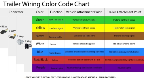
LFwQJ-QSnNM-SIsthtrailer-wiring-color-code-chart.jpg
 
I think the black with red tracer wire goes from the L terminal on the 3 prong flasher to the indicator light in the turn indicator. I could be wrong. Try supplying voltage to that wire to see if the indicator light turns on, with a fuse in the circuit. Try with the turn indicator turned to left or right too.

The switch must be grounded which is usually supplied by the steering column. The only other thing I can think of is that the wire is a ground wire. Check the resistance from that wire to the case of the switch. If it is a ground wire the reading will be very close to zero. If it is the indicator light you will see a few ohms.

On my signal switch, same type, the indicator light was not bright enough to see so I re wired the switch to use just straight voltage from the ignition switch. I put a piece of black tape in the center so I did not have to see the light on all the time.
 
Last edited:
nkaminar , I was wondering if it could be a ground myself , but you would think the directions would mention this . Also the solid black wire is to hook to the "L" terminal on the flasher according to directions
 
Sorry, it is the P terminal on the flasher that goes to the indicator light.

The wiring diagrams on the internet use a number of different colors for the wires. I think you will have to do some detective work with your ohm/volt meter.
 
Last edited:
1. Grn. wire right front ,
2. yellow left front ,
3. Brn Right rear ,
4. orn. left rear ,
5. blu. to flasher ,
6. blk to flasher
7. red to brake light switch ,
8. black with red stripe. Do you think this wire goes to battery for voltage to make this thing work?
 
MAG , I don't think so , the red wire that goes to brake light switch / then brake light switch to battery , then battery to X on flasher
 
Many of these directional signals are knock offs of the Signal Stat 900. You can find their wiring schematic on the internet. It may have the same color code. Ed
 
This is a link to instruction diagram. https://content.speedwaymotors.com/DigitalAssets/assets/testing/91062860_INS_2021_2.pdf

This is a wiring color chart for different applications. https://content.speedwaymotors.com/DigitalAssets/assets/testing/91062860_INS_2021_1.pdf
If you weren't already confused, this information will likely make things even more confusing. Evidently Speedway also provides a basic auto wire harness where this unit can be integrated into it but that isn't the case with the OP so that is part of the confusion.

Most of these types are set up with 7-wires. Some are set up for using a separate flasher for 4-ways. I'm not sure why they would do that and I can't tell you that this has anything to do with this particular switch. It could be for an external indicator or pilot light but some have a flash indicator built into the switch body so an external light would be redundant. Power for the system should be a fused wire that feeds directly into the flasher unit. Ground it provided by attaching the switch to the steering column.

Bratton's has a switch for model A cars that has 8 wires but it has completely different wire colors and the connect up is different as well. This link shows different types and the way they are wired so a person can see that they can be similar but there is always some quirk that can make a difference between them. http://cedarcreekas.org/TechTopics/TurnSignalsCollection.pdf

A person may be able to trace the unknown wire out and see what it connects to internally.
 
Last edited:
Measure the resistance between the black wire with red tracer to the switch case. If it is zero then it is a ground wire. If it has a few ohms it is for the indicator light. Most likely the indicator light. If I remember correctly I had to run a ground wire from the case to a ground point on the chassis.

The wiring diagram that Rotor Wrench supplied shows the blue wire going to the P terminal on the flasher and the black wire going to the T terminal. This may be reversed in your case, or not. Can you set this up on a bench to test it?
 
Last edited:
It may be a ground for the pilot lamp, so you don't have to scrape paint off your steering column. Check for continuity between that wire and switch housing. You could leave it off and see if it works ok. Looks like you have it wired correctly otherwise.
 
I got every thing working , I got wires going every where , nothing in place yet , without using the black/red stripe wire at all , so I don't know what it would be for . I had a bad flasher the first time I think I shorted it out , and my switch wasn't getting a good ground , Now if I can just unhook everything re rout and get it hooked back up , I'll be good to go , thank you all for your help , and if someone finds out what the B/R wire is let me know


Vern
 
Back
Top