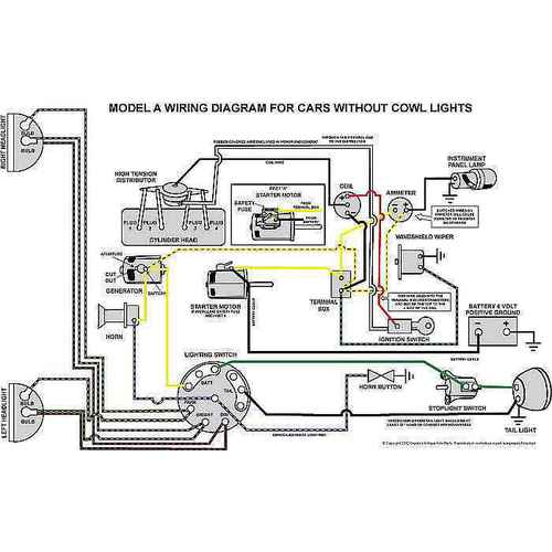
will mal-adjustment of the third brush on the generator cause a showing of a discharge on the ammeter? When I tested across the battery terminals with the car running it shows a charge, not a discharge. Ammeter gauge is wired correctly, or at least the yellow wire goes on the left side of the meter (facing it from the rear) to the generator and the tracer wire goes to the starter. It doesn't make sense to me and before I switch wires on the ammeter I thought I'd better get advice. The ammeter goes to "0" with ignition off.

You are using an out of date browser. It may not display this or other websites correctly.
You should upgrade or use an alternative browser.
You should upgrade or use an alternative browser.
Generator/ammeter question
- Thread starter akruzer
- Start date

ndnchf
Well-known member
"When I tested across the battery terminals with the car running it shows a charge, not a discharge."
I'm confused by this statement. You can measure voltage across the battery terminals, but not amperage. To measure amperage the ammeter must be inline, or in series with the battery.
Check out this video I made about adjusting the 3rd brush.
https://youtu.be/PL94VX3GIq8
I'm confused by this statement. You can measure voltage across the battery terminals, but not amperage. To measure amperage the ammeter must be inline, or in series with the battery.
Check out this video I made about adjusting the 3rd brush.
https://youtu.be/PL94VX3GIq8

nkaminar
Well-known member
Modern cars have a means of regulating the charging voltage, not the current. Measure the voltage at the battery, or more conveniently at the stud on the starter switch to ground. With the engine off you should measure about 6.3 volts (assuming you have a 6 volt battery). After the engine is started and run at a fast idle for at lease 5 minutes you should measure about 7 volts. If much lower, say 6.5 volts, or much higher, say 7.5 volts, either the generator is not adjusted correctly or there is a problem with the battery or the wiring (such as a bad ground) or a problem with the cutout. Measure the voltage at a fast idle so that the generator would normally be generating. Measure with the lights off.
If you have a 12 volt battery, double these voltages.
If you have a 12 volt battery, double these voltages.

Patrick L.
Well-known member
I'm waiting for an answer to Bob's question. Without that info it kinda seems like the ammeter is wired backwards.

rotorwrench
Well-known member
Ammeters such as used in automotive & ag equipment applications really only have a charge side and a discharge side. The polarity gets confused when going from 6-volt positive ground to 12-volt negative ground systems but charge and discharge don't change. In the case of the OEM model A and others like it, charging comes from the generator. The battery is related to the charge side. This puts the ammeter in series with the feed from the generator to the battery. The power feeds circuits for accessory are generally connected off of the generator feed line so that they can show discharge when circuits are activated. The starter is an exception. It draws too much current to be part of the charging circuit.
I use the MAFCA wiring diagram pdf for reference. It tells the story pretty well.
Modern ampmeter reproductions are not my favorite parts. I prefer the old originals withe the C shaped magnet inside. They are much more sensitive than any reproductions I've come across.
I use the MAFCA wiring diagram pdf for reference. It tells the story pretty well.
Modern ampmeter reproductions are not my favorite parts. I prefer the old originals withe the C shaped magnet inside. They are much more sensitive than any reproductions I've come across.
Last edited:
"Ammeter gauge is wired correctly, or at least the yellow wire goes on the left side of the meter (facing it from the rear) to the generator and the tracer wire goes to the starter"
Ak, IMHO, this comment is incorrect.
Assuming you have and American car with the driver on the left as viewed from the drivers seat:
the solid yellow wire attaches to the discharge side of the ammeter as labeled on the front side of the gauge, then to the passenger side of the terminal box and from there to the starter switch stud.

The yellow / black stripe wire runs from the generator / alternator to the driver side of the terminal box and then to the charge side of the ammeter as labeled on the front of the ammeter.
From the drivers seat, the ammeter reads from left to right, discharge / charge.
Ak, IMHO, this comment is incorrect.
Assuming you have and American car with the driver on the left as viewed from the drivers seat:
the solid yellow wire attaches to the discharge side of the ammeter as labeled on the front side of the gauge, then to the passenger side of the terminal box and from there to the starter switch stud.
The yellow / black stripe wire runs from the generator / alternator to the driver side of the terminal box and then to the charge side of the ammeter as labeled on the front of the ammeter.
From the drivers seat, the ammeter reads from left to right, discharge / charge.
Last edited:

rotorwrench
Well-known member
There seems to have always been confusion on how to connect the ammeter and most of that is due to no identification or mis identification of the terminals in the diagram drawings or because folks have them connected wrong in photographs. The charge side is the flow of amperage to the battery terminal. The generator is where the flow comes from to charge the battery. Most vehicles have an electrical buss where there are fuses to all the electrical components. The generator feeds the buss as long as it is operational. When the battery is the only thing feeding the buss, the flow reverses and shows a discharge if any electrical component is energised. The buss is shared with the battery so that it can get charging amperage. The direction the current flows is captured by the ammeter and indications reflect that.
The model A predates the use of a buss so the terminal box is about as close as it gets. A person can connect electrical components on the battery side of the ammeter but it won't register flow through the ammeter since it's wired straight out of the battery. Ford published a service bulletin to rewire the ignition coil in the early part of the model A era so that the coil would register on the ammeter. It is a good troubleshooting aid to see that the ignition system is functioning normaly while energizing the starter.
The model A predates the use of a buss so the terminal box is about as close as it gets. A person can connect electrical components on the battery side of the ammeter but it won't register flow through the ammeter since it's wired straight out of the battery. Ford published a service bulletin to rewire the ignition coil in the early part of the model A era so that the coil would register on the ammeter. It is a good troubleshooting aid to see that the ignition system is functioning normaly while energizing the starter.