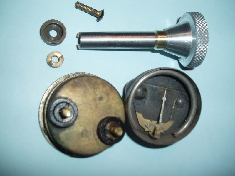
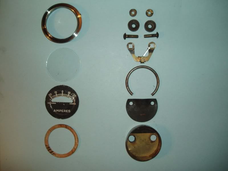
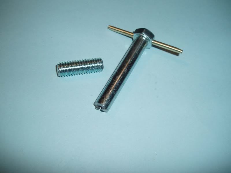
I have attached a photo of the generator cutout on my 30 Tudor. I would appreciate hearing from any who can ID the Standard Motor Products cutout and tell me whether this was a common replacement and the general time frame it was sold and used.
Also, and more importantly, one of the wires to my ammeter got hot enough to burn the insulation and damage the ammeter, which permanently registers a 10 on the discharge side of the scale whether the motor is running or not, and whether the battery is disengaged or not. I replaced the entire loom between the terminal box and the instrument panel, and I added a fuse to avoid a similar problem. However, I wonder whether the generator cutout may have played a role.
Could any explain how I can use a multimeter to test the ammeter? I am not electrically-inclined, so I would need very basic instructions. I tried to use the multimeter while the engine was running by touching the black lead to the screw on one side of the cutout and the red lead to the screw on the other side, with the multimeter set to read between 3 and 10 volts. Nothing showed on the meter. I then switched the leads to the opposite screws, and still nothing showed.
The car runs well now that I've added the fuse and replaced the instrument wire loom. But I would like to make sure that the generator cutout is doing what it is designed to do. It also might make sense to replace the cutout with something that looks a little more stock. Is the diode replacement a wise choice?
Also, and more importantly, one of the wires to my ammeter got hot enough to burn the insulation and damage the ammeter, which permanently registers a 10 on the discharge side of the scale whether the motor is running or not, and whether the battery is disengaged or not. I replaced the entire loom between the terminal box and the instrument panel, and I added a fuse to avoid a similar problem. However, I wonder whether the generator cutout may have played a role.
Could any explain how I can use a multimeter to test the ammeter? I am not electrically-inclined, so I would need very basic instructions. I tried to use the multimeter while the engine was running by touching the black lead to the screw on one side of the cutout and the red lead to the screw on the other side, with the multimeter set to read between 3 and 10 volts. Nothing showed on the meter. I then switched the leads to the opposite screws, and still nothing showed.
The car runs well now that I've added the fuse and replaced the instrument wire loom. But I would like to make sure that the generator cutout is doing what it is designed to do. It also might make sense to replace the cutout with something that looks a little more stock. Is the diode replacement a wise choice?