Test Results - Crab Dist on my Allen Synchrograph

Ziggster

Well-known member
Finally got through “testing” a non-rebuilt/as-is Crab distributor on my Allen Syncrograph (Model E-316HD). I purchased this machine 5 yrs ago in Rochester, NY and. Only got around to actually seeing if it truly worked starting last week. I mentioned in this thread, that I would follow-up with my observations.

https://www.fordbarn.com/forum/showthread.php?t=351398

I’m a complete novice when it comes to testing these types of distributors, and it was a bit of a steep learning curve, and still is. The machine has issues such as a burnt out neon bulb (one of two), a non-functioning tach (works but is inaccurate), but despite those issues I was still able to get speed data with an optical tach, and the one bulb was just sufficient to read the flashes on the degree wheel.

I did purchase a photocopy of the manual off of eBay several years ago, but it was of poor quality in terms of quality of images, cropped pages, and missing pages. I did find other copies of the manual on-line, as well as other literature related to the Allen Syncrographs. I’m willing to share that info with others who request it to help support those who are going through what I just went through trying to get this one working. I do have this thread on the HAMB as well going over them”restoration” of the machine, including the results, but will summarize just the test results in this thread.

https://www.jalopyjournal.com/forum/threads/allen-syncrograph-model-e-316hd-resto.1217704/page-4

I’ll post details of the results later this morning hoping it will prompt experienced folks with these machines/distributors to comment on what I measured, what I did right, and what I did wrong. Haha!
 
Allen Syncrograph (Model E316-HD). Circa 1953?
 

Attachments

  • IMG_9613.jpg
    IMG_9613.jpg
    52.7 KB · Views: 43
Crab distributor as tested. It came from one of my two C59A industrial engines.
 

Attachments

  • IMG_9614.jpg
    IMG_9614.jpg
    61 KB · Views: 18
  • IMG_9615.jpg
    IMG_9615.jpg
    56.5 KB · Views: 18
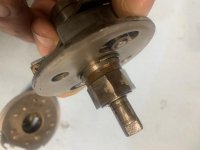
Some close up pics of the distributor dis-assembled after the test. The bronze bearings don’t look the very best, but there was no noticeable slop or binding of the main shaft. It was all re-assembled with fresh grease/machine oil.
 

Attachments

  • IMG_9619.jpg
    IMG_9619.jpg
    40.5 KB · Views: 12
  • IMG_9620.jpg
    IMG_9620.jpg
    44.4 KB · Views: 12
  • IMG_9621.jpg
    IMG_9621.jpg
    38.3 KB · Views: 12
  • IMG_9622.jpg
    IMG_9622.jpg
    33.1 KB · Views: 11
  • IMG_9623.jpg
    IMG_9623.jpg
    38.1 KB · Views: 10
More pics.
 

Attachments

  • IMG_9624.jpg
    IMG_9624.jpg
    42.5 KB · Views: 13
  • IMG_9625.jpg
    IMG_9625.jpg
    26.8 KB · Views: 14
  • IMG_9626.jpg
    IMG_9626.jpg
    38.9 KB · Views: 12
  • IMG_9627.jpg
    IMG_9627.jpg
    44 KB · Views: 15
  • IMG_9628.jpg
    IMG_9628.jpg
    57.1 KB · Views: 14
Another batch of pics.
 

Attachments

  • IMG_9629.jpg
    IMG_9629.jpg
    66.1 KB · Views: 9
  • IMG_9630.jpg
    IMG_9630.jpg
    49.2 KB · Views: 8
  • IMG_9631.jpg
    IMG_9631.jpg
    27.7 KB · Views: 8
  • IMG_9632.jpg
    IMG_9632.jpg
    24.1 KB · Views: 10
Last batch. Took pics of the cam as it looked not the best, but this wear seemed to have no affect from what I saw on the tests.
 

Attachments

  • IMG_9633.jpg
    IMG_9633.jpg
    47.6 KB · Views: 15
  • IMG_9634.jpg
    IMG_9634.jpg
    36.6 KB · Views: 15
  • IMG_9635.jpg
    IMG_9635.jpg
    33.4 KB · Views: 14
  • IMG_9636.jpg
    IMG_9636.jpg
    32.2 KB · Views: 13
  • IMG_9637.jpg
    IMG_9637.jpg
    32.7 KB · Views: 13
Initially set both points to 0.014”. All points and electrical
contact surfaces were cleaned using 600 grit paper.

Found that at 0.014”, dwell was 25 degrees.

Went to larger gap, and this is what I found:

0.020” - 13.5 degrees
0.018” - 16 degrees
0.016” - 24 degrees

Since largest recommended gap is 0.016”, I decided to leave it at that. Mike Driskell in his YT vid testing the helmet style on his Sun machine said he aimed for 22.5 degrees. I figured for my “test” purposes this was close enough. This for the left hand side (driver’s side set of points. The other set were blocked off with a piece of paper.

With the right-side set of points gaped at 0.016, measured the dwell at 31 degrees. Thought it was 34 degrees as stated in my thread on the HAMB, but checking my notes it’s 31. IIRC, Mike shoots for 34 degrees. Again, figured this was close enough for what I was trying to achieve.
 
Next was checking the advance. So, continuing with the test, with no other changes to the distributor. Should note that the advance setting on the side of the hsg was set to “0”.

Here are the results:

500 rpm - 3.5 degrees
750 rpm - 8 degrees
1000 rpm - 10.5 - 11 degrees
1250 rpm - 11 degrees
1500 rpm - 11 degrees


Note this is cam rpm, so engine rpm would be double.
 
Next, decided to see what happened when I advanced the timing using the adjustment screw on the side of the hsg. Advanced it all the way, and got another 4 degrees of advance, for a total of 15 degrees of advance, but as soon as I went to tighten down the screw, I could see the base plate with the points move towards the vacuum brake side of the housing, and advance would return to about 10 - 11 degree. I couldn’t believe what I was seeing. Tried several times, and each time as I tightened down the adjustment screw, the timing would “retard” by the amount it was advanced. Not sure if this is typical (I hope not!), or something particular to just this distributor. The snap ring for the base plate was in place, so not sure why or what is really going on.
 
Last was to test the vacuum brake. However, I couldn’t test it because the “o-ring” on the rear of the housing didn’t seem to seal against the drive adapter, as I could not pull much if a vacuum according to the meter on the machine, so I gave up on that.

This is all I have to report so far, and welcome any comments. A buddy of mine says he has the caps to replace which are in the tack circuit, as well as possible neon replacement bulbs. Might be able to meet him in a few weeks which would be great. In the mean time, I plan on testing the helmet style distributor which I rebuilt for my speedster.
 

Attachments

  • IMG_9602.jpg
    IMG_9602.jpg
    26.4 KB · Views: 11
  • IMG_9603.jpg
    IMG_9603.jpg
    34.1 KB · Views: 11
Last was to test the vacuum brake. However, I couldn’t test it because the “o-ring” on the rear of the housing didn’t seem to seal against the drive adapter, as I could not pull much if a vacuum according to the meter on the machine, so I gave up on that.

I just tested my crab vacuum brake with a vacuum pump and a modified air filler cone. vacuum brake piston should lift at 5" of vacuum.

From an friend in our local V8 club

573188


https://www.fordbarn.com/forum/showpost.php?p=2409272&postcount=29
 
Last edited:
One additional refurb you should do is to remove and clean the oiling wick. It delivers oil to the upper shaft through a small hole there. Soak the wick in solvent and then roll it out a few times until it is clean, then re-oil before reassembly.

There are two types of caps for the wick, a threaded plug and a cap, like a mini freeze plug.

573168


This shows how I pulled the cap type which I then replaced with a threaded plug

573172


573170


573169


These are the wicks. Note the length difference for the two cap types

573173


573174
 
Back
Top