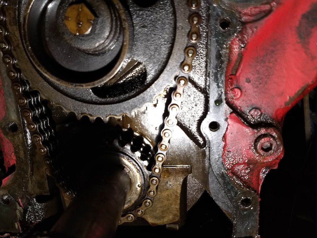
56 T-bird rebuild

So when the timing marks are in the proper position where should I expect the rotor to be pointing?
. . . Are the marks not TDC for #1 cylinder?
Ignore the position of the distributor rotor.
The "12 pins between the marks" position on the crank & cam gears is not related to cyl #1 TDC.


.
 
Last edited:
Okay after watching the video it looks like the rotor should be 180 from #1 when the timing marks are in the correct position. Should I just change the chain or put a set on it?
 
Your assumption is incorrect. When the rotor is at the # 1 wire spot on the distributor the pointer should line up with the timing mark at the pulley. At this position, both rockers on # 1 cylinder should be loose (valve lash). This is top dead center. The chain is probably ok (but looks loose) - you have to remember that the crank goes around twice in relation to the cam.


As dmsfrr said, don't confuse the chain marks with setting up the distributor at TDC


Remember #1 cylinder is the front cylinder on the right (passenger side of the engine.


Okay after watching the video it looks like the rotor should be 180 from #1 when the timing marks are in the correct position. Should I just change the chain or put a set on it?
 
Last edited:
My only suggestion is Take LOTS of pictures, lots of close ups. I am helping a friend with a 55 bird. Right now we are trying to figure out how to put the windshield back in. Yes did all the rope stuff. There are two metal spacers or something. We think they go between the rubber and the metal frame, but the lower rear corners do not fit all the way down. So take lots of pictures, then take more.
Steve
 
Okay after watching the video it looks like the rotor should be 180 from #1 when the timing marks are in the correct position. Should I just change the chain or put a set on it?
With the crank and cam gears in the "12 pin"/installation position, yes I think cyl #1 is approx BDC and the distributor rotor points near to the #6 wire.
If you're going to replace the chain, change the gears too. They wear-in to each other.
FYI, the crankshaft key is at approx 7 o'clock when cyl #1 is at TDC. (photo 1 below)

Your assumption is incorrect. When the rotor is at the # 1 wire spot on the distributor the pointer should line up with the timing mark at the pulley. . .
. . . don't confuse the chain marks with setting up the distributor at TDC.
You won't be able to line up the distributor cyl #1 rotor position, timing pointer and TDC on the crank pulley until the front of the engine is back together.
.
 

Attachments

  • crank keyway, #1 TDC.jpg
    crank keyway, #1 TDC.jpg
    95.6 KB · Views: 17
  • timing marks, c.jpg
    timing marks, c.jpg
    61.9 KB · Views: 14
Last edited:
Okay after watching the video it looks like the rotor should be 180 from #1 when the timing marks are in the correct position.

Should I just change the chain or put a set on it?

You are overthinking.

Setting the timing chain on this style engine has nothing to do with IGN timing. You are merely timing the cam to the crank.

Once assembled with the timing cover and pointer can you verify/set the IGN timing (verify correct dist rotor position).

It is also a good practice to verify possible balancer outer ring slippage and true TDC.

You replace the timing set in this instance.
 
All I know is when I took it apart I made it a point to set the timing mark on the balancer at what I thought was TDC and then just looked to see where the rotor was in relation to that and it was pointing at #1 but apparently that has nothing to do with the setting of the marks of the cam and crank. I'll roll crank gear over to where it should be by the pics and diagrams and see where the cam is then.
 
All I know is when I took it apart I made it a point to set the timing mark on the balancer at what I thought was TDC and then just looked to see where the rotor was in relation to that and it was pointing at #1 but apparently that has nothing to do with the setting of the marks of the cam and crank.

I'll roll crank gear over to where it should be by the pics and diagrams and see where the cam is then.

You are correct in your thinking except REGARDING the FYB. It is timed (cam/crank) in another fashion for whatever reason. As long as the gears/chain is timed per the manual, simply button it up.

Find #1 cyl compression stroke and align timing marks. Then you check DIST rotor position.

Does that help or am I just adding to the confusion ... :confused:
 
Don't think so. The cam and crank are lined by their marks and the balancer is marked for TDC for ignition so that the rotor is then aligned with #1 wire. Regardless the first step is to put the two gears and pin count correct. If all is right when I put it back together and put the balancer to TDC then the rotor will be positioned right.
 
. . . the first step is to put the two gears and pin count correct. If all is right when I put it back together and put the balancer to TDC then the rotor will be positioned right.
Yes.
For whatever reason, when Ford made the Y-block engines the timing gear marks and installation procedure are not related to the position of the piston in cyl #1.

If the crank & cam shaft keyways, dots on the crank & cam gears and the pin count on the timing chain matches the diagrams, it is correct.

Make sure you have the correct style timing pointer and locate the timing marks on the rear lip of the crank pulley.
If the damper ring is close to slipping off the shoulder of the pulley hub (photo 2) the pulley needs to be rebuilt (photo 3).
.
 

Attachments

  • timing marks, c.jpg
    timing marks, c.jpg
    61.9 KB · Views: 10
  • bad T-bird pulley.jpg
    bad T-bird pulley.jpg
    47.3 KB · Views: 18
  • 1 crank damper pulley.jpg
    1 crank damper pulley.jpg
    23.2 KB · Views: 21
Last edited:
The seal in the timing cover that rides on the small end of the damper pulley hub will often wear a groove in it, or the small end of the hub may be pitted from rust (photo 1 below). The repair sleeve goes over the end of the damper pulley hub to provide a new surface that is less likely to leak. The damper pulley in photo 3 above has a sleeve installed.
.
 

Attachments

  • y-block truck pulley.jpg
    y-block truck pulley.jpg
    33 KB · Views: 9
  • T-Bird pulley with loose damper ring.jpg
    T-Bird pulley with loose damper ring.jpg
    48.4 KB · Views: 14
Last edited:
Crank looks good. But from this photo it looks like it was timed right.
The seal in the timing cover rides on the small end of the damper pulley hub, not the crankshaft.

If that's the keyway for the crankshaft timing gear I'm seeing just above & left of the small circular mark on the gear... the timing marks and pin count look right to me too.
.
 
Last edited:
We have cam timing and ignition timing all in one thread here. Try not to mix the two up since one has no affect on the other. Cam timing just sets the cam to time with the crankshaft so that valves open & close at the correct intervals.

Ignition timing is strictly to synchronize the distributor with the position of the piston on each compression stroke starting with number 1 cylinder. On a 4-stroke engine, the timing position marker will align with the lower pulley timing mark twice for a complete firing cycle. One will be TDC on end of compression stroke and the other will be TDC on end of exhaust stroke. Always make sure it's on the #1 compression stroke when checking distributor/ignition timing. It should be blowing air out the #1 spark plug hole when coming up on compression while being rotated in normal direction of rotation.
 
We have cam timing and ignition timing all in one thread here. Try not to mix the two up since one has no affect on the other. . . . .
On some other makes/models of engine that are more common than Y-blocks the crank & cam timing chain marks can be in line with each other and may also do double duty and are related to cyl 1 TDC...
But not on the Y-block engine.

To someone more familiar with these other engines
the Y-block timing chain installation seems somehow 'wrong', leading to all this confusion.

The still image attached below is for another model of Ford engine, from the video link posted by KULTULZ, at approx 20 seconds.
It applies to at least one other well known make of engine as noted in the narration of the video. :rolleyes:

https://www.youtube.com/watch?v=b1Z2L9pgMXU
 

Attachments

  • timing marks in-line.jpg
    timing marks in-line.jpg
    67.1 KB · Views: 15
Last edited:
Back
Top