New model B distrib cam

Bill Goddard

Well-known member
I am participating in a distributor rebuilding seminar next month and I need some info on the new distributor cam being sold by Bratton's and others. I understand the cam profile has been modified from the original and allows the cam follower on the point set to run smoother thus increasing the useful life of the follower. Does anyone have a picture of the new cam profile like an end view or a comparison of the old and new cams? I know this is a tall order but there must be something out there somewhere.

Thanks Bill G
 
DistributorCamsAandB.jpg


This is the same photo I recently posted about the distributor cams. This is the only one I have comparing the two cams and showing the profiles.

With the correct .020" points gap the Model A cam has 27* dwell and the Model B cam has 40* dwell.

Dwell is the time the points are closed and current is being sent through the coil primary windings, building up a strong magnetic field. This action ISN'T instantanious, so the more time the points are closed the more time the coil has to build a magnetic field. This becomes more of an issue with V8's than it is with only 4 cylinders.

When the points open the magnetic field rapidly collapses, which induces a current flow into the secondary windings, which is enough to jump the gap of the rotor and cap, plus the gap of the spark plug.

The collapsing magnetic field also induces a fairly high voltage into the coil primary, which would arc across the points and burn them if the condensor wasn't in the circuit to absorb the surge of current. The capacitor then sends the current back through the coil primary and induces high voltage again into the secondary windings. This "tuned circuit" continues to bounce back and forth until the voltage is no longer high enough to fire the spark plug. This pattern is easily seen on an engine scope, and I'll find my picture of that and post it also.
 
Last edited:
Condenser3.jpg


Here's a picture of the secondary circuit as seen on an engine scope. Notice the high voltage occilations on the left showing when the volatage is high enough to fire the spark plug. When the seconday circuit can no longer fire the plug, the occilations continue to dwindle until the points close again and the coil starts to build up another magnetic field for the next firing.

You will notice that I have the scope set to show all 4 spark plug firings at the same time. That's why you can see 4 patterns on top of each other.
 
IgnitionTester.jpg

Condenser1.jpg

Condenser2.jpg


Here's a scope picture of the coil primary circuit showing the voltage pulsing through the condensor. On the right side of the picture you will see the line drop when the point close.

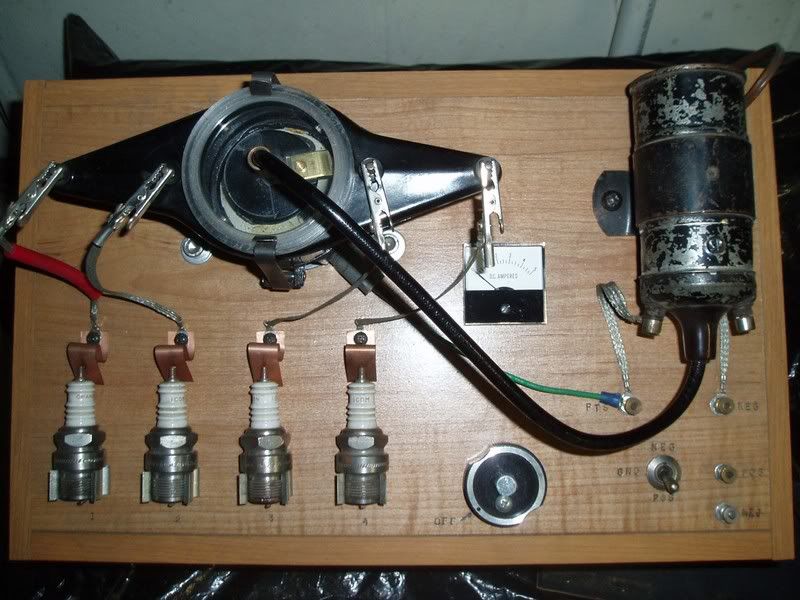
The middle picture shows my Heathkit scope I bought at a swap meet. The first picture shows the tool I made for checking distributors and cams. I can also swap out coils and condensors to test them, but I made a smaller easier to use tool mainly to do that.
 
Hey Tom, can you tell anything on the scope when you swap in the counterweighted rotor?

Also, what would happen if you were to enclose the spark plugs in a tube that is pressurized to about 50 psi?? Thoughts??

BTW Bill, you need to get with Bill Stipe regarding the cams since he makes the best one.
 
Hey Tom, can you tell anything on the scope when you swap in the counterweighted rotor?

Also, what would happen if you were to enclose the spark plugs in a tube that is pressurized to about 50 psi?? Thoughts??

BTW Bill, you need to get with Bill Stipe regarding the cams since he makes the best one.

I have only run REBUILT distributors in my car and in this testing machine. A balanced rotor should help to prolong the life of the bushings, just like counterweights on the crankshaft lessen the load on the babbit, thus prolonging the life of the babbit. The next time I play with this machine I'll have to install a distributor with worn bushings and take a picture of the scope pattern. That will be this winter.

If I pressurized the plugs the scope would show a bit higher and shorter pattern during the firing portion. That's because the more pressure, the higher the voltage required to fire the gap.
 
Last edited:
Back
Top