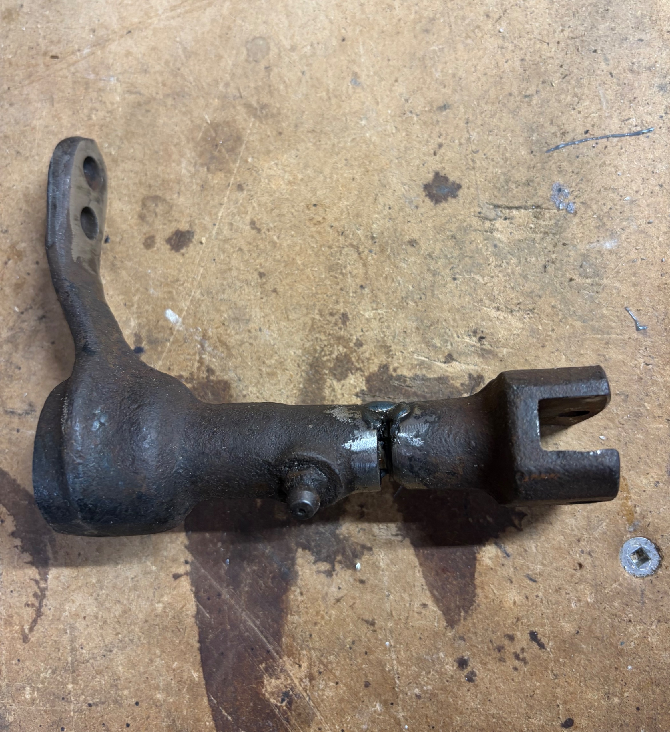
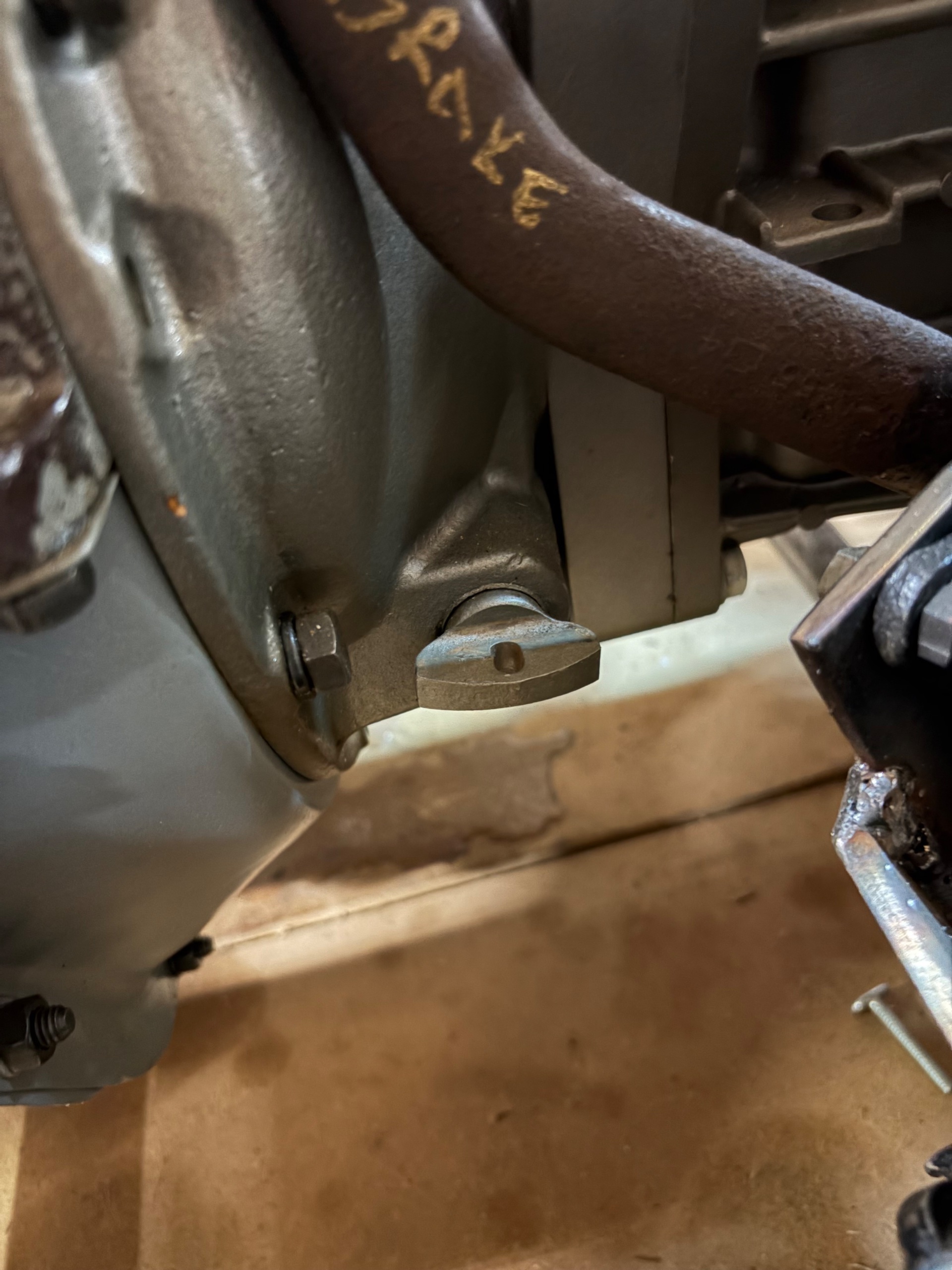
I’m in the process of mocking up my pedal assembly (1940) to my C59A. I have the engine attached to the trans and I need to know what the correct orientation for the flange on the shaft for the clutch forks. I don’t have the clutch/pressure plate/throw-out bearing installed. I’ve modded the corresponding shaft from the pedal assembly by shortening it. So, before proceeding further, I need to understand how to index the mating flange on the shaft.

You are using an out of date browser. It may not display this or other websites correctly.
You should upgrade or use an alternative browser.
You should upgrade or use an alternative browser.
Help needed - Orientation of clutch shaft
- Thread starter Ziggster
- Start date

19Fordy
Well-known member
Look thru here. I think it will help., Open and scroll down.
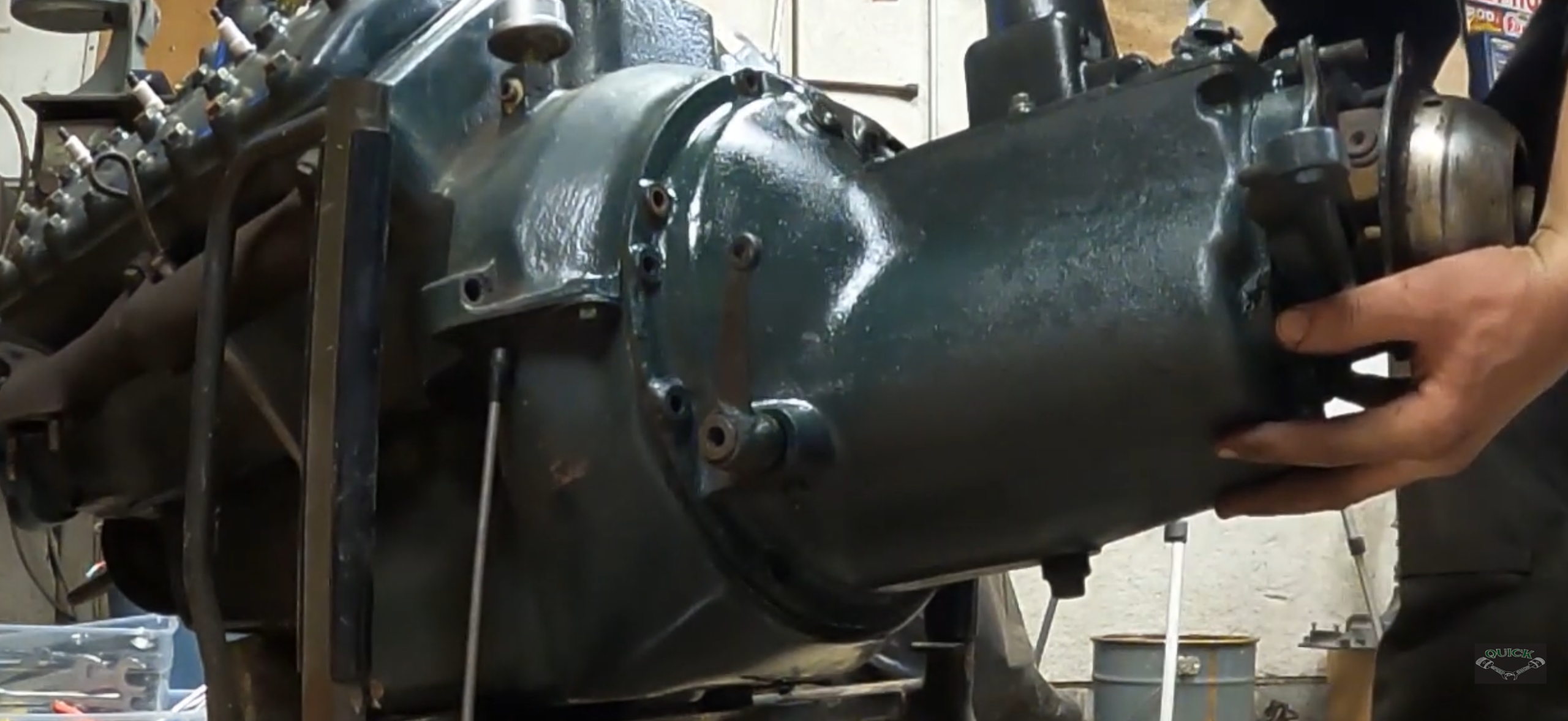
Thanks for all the links. I quickly went through them all and didn’t see anything that was helpful. Did my own internet search, and came across this vid, but it also did not show the type of cross-shaft flange I’m looking for.
It and brought me to one of my threads on the HAMB. Lol!

 www.jalopyjournal.com
It and brought me to one of my threads on the HAMB. Lol!
Technical - C59A Ford Flathead & Ford T5 (1994+)
As I get a little closer to wrapping up work up on my Flathead, I’m looking into what I need to do to attach it to my Ford T5. I purchased the T5 a few...
www.jalopyjournal.com
Thanks for the pics. That’s a long lever arm. Looks like the one that came off of my second C59A that had an 11” clutch.
What I’m interested is the orientation of the mating shaft flange that goes through my hog’s head adapter with the forks when pressure plate is not depressed.
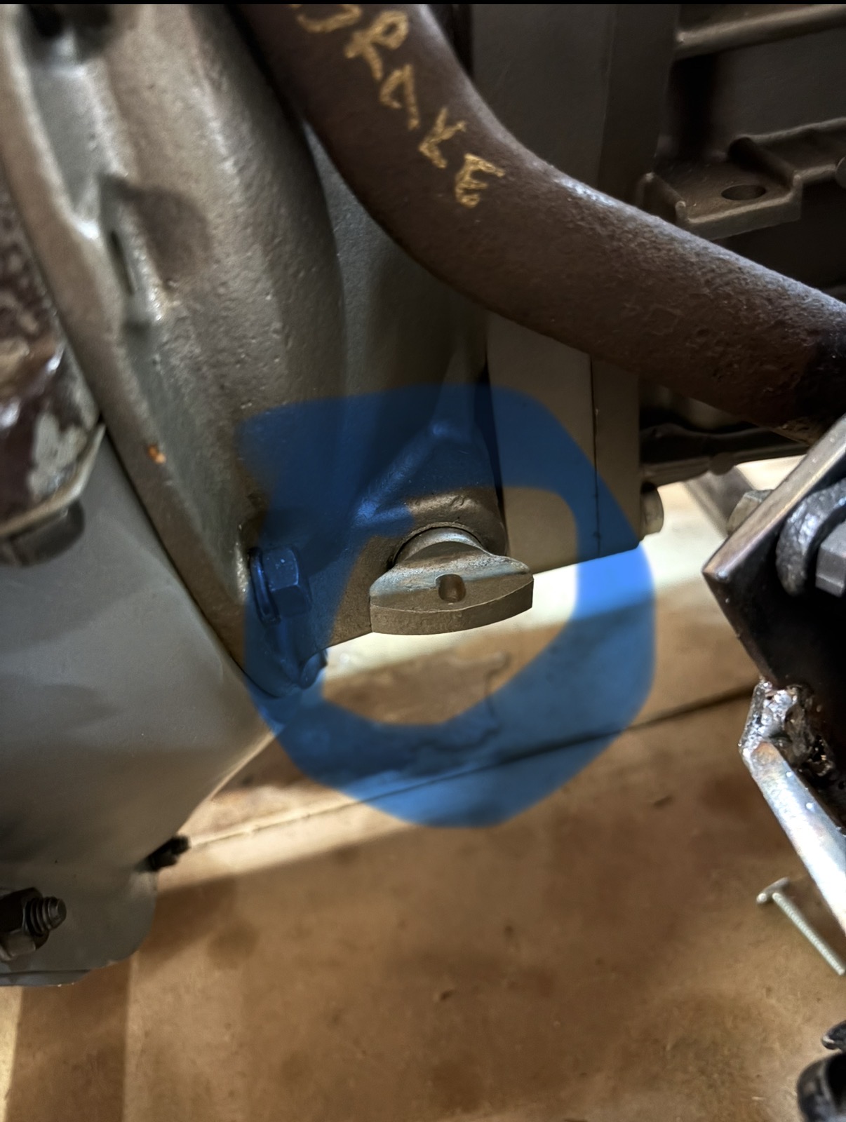
What I’m interested is the orientation of the mating shaft flange that goes through my hog’s head adapter with the forks when pressure plate is not depressed.

Karl Wolf
Well-known member
I was taking a guess that the geometry would be the same as 1946-48, and -I think- through 1953 (?).
You might assemble all, and turn the operating shaft as it would go to release the clutch.
See if all seems to use the same geometry. I would think it would.
I have three of these pictured parts, they are same, and I think they all came from cars.
Karl
You might assemble all, and turn the operating shaft as it would go to release the clutch.
See if all seems to use the same geometry. I would think it would.
I have three of these pictured parts, they are same, and I think they all came from cars.
Karl
I can’t assembly it yet as I need to get my flywheel machined to accept a 9.5” clutch that I just picked up. Flywheel was machined for an 11” clutch originally. Before taking the flywheel out, I would like to get the orientation of the shaft sorted out so I can continue on with mocking up the pedal assembly.